Templates for Wiring Diagrams for Devices
Wiring diagram templates allow you to define the exact appearance of the wiring diagram for a device. You define the terminal layout and graphical appearance using a drawing editor. You can arrange terminals in any positions that you require. You can draw any extra graphical information that you require.
NOTE: You should only use templates for wiring diagrams when you need a layout that cannot be produced by a standard constructed wiring diagram. Generally the standard device terminal layout or the MTD terminal layout should be sufficient for most devices.
Wiring diagrams created from templates
When the wiring diagram is constructed, the template is inserted directly into the drawing. The attributes of the symbols inside the inserted template are updated to hold the information from the device and its terminals.
Wiring diagram templates for devices will be rotated as required when inserted.
Template files
Wiring diagram templates are drawing files containing wiring diagram symbols. There is no requirement for the names of the template files, however since they co-exist with MTD symbols you should use a file name that makes the templates easy to identify. For example, you could prefix all wiring diagram templates with "wd_".
The templates are stored in the same directories as MTD symbols:
-
<EDS>\MET_GMTD for metric symbols
-
<EDS>\IMP_GMTD for imperial symbols
Do NOT copy or rename a wiring diagram template with the file system of your computer. The name of the graphical elements block within the template is expected to be related to the name of the template. Copying or renaming a template breaks this relationship. The MTD Name function enables copies of templates to be made correctly.
Drawing wiring diagram templates - MTD editor
A wiring diagram template is created using the same tool that creates Multi-Terminal Device (MTD) symbols. The MTD editor is part of Elecdes. Wiring diagram templates contain different component symbols from MTDs. The following is an outline of the procedure to create or edit a wiring diagram template. For full instructions, refer to How to Create a Device with a Custom Terminal Layout (Elecdes).
-
Select Create/Edit Multi-Terminal Devices from the Elecdes main menu.
NOTE: You must always use Create/Edit Multi-Terminal Devices to edit an existing wiring diagram template. If you were to open the file manually from the CAD package then Elecdes would not know you were editing a template and would not re-build the graphical elements block when you save the file.
-
You will be provided with a list of existing MTD symbols and wiring diagram templates.
Select one of the wiring diagram templates for editing OR enter a new name for the new template.
-
The chosen drawing will be opened.
-
Use the MTD toolbar items to insert a single wiring diagram tag symbol and wiring diagram terminal symbols on the template.
-
Draw any graphical parts of the template that you require. You can use simple entities such as lines, arcs and circles as they will be grouped automatically into a block when you save the template.
NOTE: You must include at least one drawing entity for a graphical elements block, even if it is on an invisible layer. Wirediag will read the insertion point of the graphical elements block to position the diagram when it is refreshing an existing diagram.
-
When you have completed editing the template, save the file with the SAVE command of the CAD package. Elecdes will intercept this command to prepare the drawing for use as a wiring diagram template.
-
The graphical parts of the template will be grouped into a graphical elements block. The block name will be based on the template name.
-
You will be asked for the insertion base point for the template.
-
The symbol will be saved in the MTD directory, as described above.
-
The template drawing will be closed.
Table of Connections
Typical Wiring Diagram Device templates show a graphical representation of the device, and show wiring to this graphical representation (determined by the terminal symbol placement on the template).
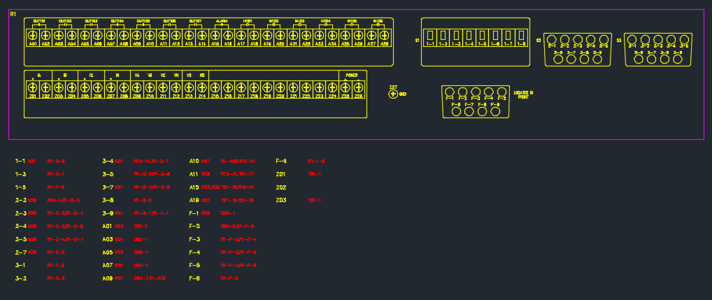
Alternatively, you may wish to show the graphical representation separately, with a table or list of only the connected terminals shown above, below or beside the graphics, in a table form (or other arrangement). For example:
Or you may want a hybrid layout with some terminals on the graphic, and some terminals in a table.
To create a table of connections, you need to insert wdAt.dwg symbols onto Wiring Diagram Template of your device:
-
wdAt symbols act as place-holders, and will be populated with the data for any terminals that have a connection and that do not match any regular terminal symbols in the template. These terminals will be sorted alphanumerically.
For a hybrid configuration, simply include both regular terminal symbols (for those you want wired directly) and placeholder wdAt symbols (for those you want in a table) in the template.
wdAt symbols contain an ALPHASORT attribute, that specifies which terminal (from the alphanumerically sorted list described above) will be associated with each terminal symbol.
-
Each wdAt symbol in the template should have ALPHASORT set to an integer value, beginning with 1, and incrementing by 1 for each successive wdAt symbol.
The TERM attribute should be left blank on these symbols in the template (it will be filled in by the Wiring Diagram Generator when the template is inserted).
-
Position multiple wdAt symbols in a table-like arrangement in the template (a table is not mandatory, the symbols can be placed anywhere). You may wish to use AutoCAD copy and paste or Array commands to assist with this.
Set ALPHASORT on the symbols according to the order they should be matched to the sorted terminal names. For example, you may wish to fill columns first:
1 4 7 10 2 5 8 11 3 6 9 12 Or rows first:
1 2 3 4 5 6 7 8 9 10 11 12 When the Wiring Diagram template is inserted, if there are more placeholder symbols than there are connected terminals to match to them, then any symbols that are unused will have their attributes blanked (and so will be invisible, if there are no graphical elements in the symbol).
Templates that use the wdAt symbols are intended specifically to show only the terminals that have connections. If you want to show all of the terminals, but in a table, create a regular template with the standard wdLt or wdRt terminals, but place them outside of the device graphic rather than inside of it.
Two sample Device WD templates with Tables of Connections (for a Schweitzer device) can be found in the MET/IMP_GMTD folder of the EDS installation:
- WD_SEL351S_CON_2U_TBL.dwg
- WD_SEL351S_CON_2U_TBL_HYBRID.dwg
Linking a wiring diagram template to a device - WD_TPLT
As a device is linked to its WD template via its catalog record, a device using a WD template must itself have valid catalog data. Enter the file name of the template for a device into the WD_TPLT column of the catalog record for that device. You do not need to enter the directory or the ".dwg" file extension.
You can use a single WD template for several devices, if they share a common terminal layout.
Once the template is created and specified in the WD_TPLT column of the catalog, it will be used automatically when the wiring diagram is generated.
You can specify more than one template choice for a device. Enter all of the template drawing names into the WD_TPLT column, separated by semicolons. If you specify multiple template options, Wirediag will attempt to choose the template with the most "similarity" between the filename of the template and the filename of the schematic symbol.
Drawing cables in columns on large templates
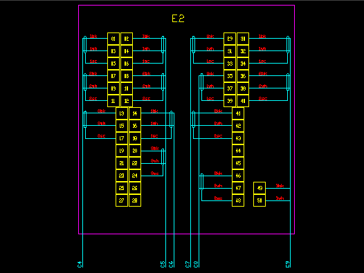
The wiring diagram template for large multi-function devices may show the terminals in multiple columns or rows. When terminals are shown in multiple columns or rows, the cable lines are likely to draw over the top of adjacent terminals. It is desirable to draw the cable lines close to each column or row of terminals instead of drawing the cable lines outside the boundaries of the template.
To specify that the cable lines should be drawn individually for each column or row of terminals, certain new attributes should be added to the wdTag symbol that is then inserted into the template.
These attributes should be set to appropriate values in the tag symbol in the original template file. The wiring diagram generator does not currently read back the values from an existing diagram.
The tag symbol wdTag101 is provided with these additional attributes, as an example. You may add these attributes to your own tag symbol(s) to achieve the same functionality. You should then set values appropriate to the layout of your template.
The additional attributes for the wdTag symbol are as follows:
-
COLTOL: This attribute is used to specify the tolerance for misalignment in position of terminals that are to be considered as one column or row for the purpose of drawing cables for columns of terminals.
The COLTOL value is measured in drawing units. For example, if the value "5" for metric or "0.1875" for imperial (3/16") is entered then the wiring diagram generator will group any terminals that are within 5mm or 3/16" of each other. The wiring diagram generator will then draw the cable lines for each grouped column or row of terminals independently of the other columns or rows.
The COLTOL attribute is optional. If this attribute is not used then the cables will be grouped for all of the terminals instead of individual columns of terminals.
-
1STCABDIST: This attribute is used to specify the distance between the first cable line and the column or row of terminals for which the cable is drawn.
The 1STCABDIST attribute is optional. If this attribute is not used then the first cable line will be drawn at one "cable offset" from the end of the conductor symbol.
-
CABOFFSET: This attribute is used to specify the distance between cable lines when cable lines are drawn for columns of terminals on a template.
The CABOFFSET attribute is optional. If this attribute is not used then the cables will be separated by the current Cable Offset (L) setting from the wiring diagram generator T-Strip Setup page.