IO Wiring Macro Symbol Changes
PLC Wizard wiring macros are groups of symbols and lines representing an IO arrangement that is suitable for 1 channel of an IO card. They are "nested blocks" that contain multiple standard Elecdes symbols. When a macro is inserted by PLC Wizard it will be exploded to its component parts. PLC Wizard will load the attributes that it has derived from your PLC Wizard data entry.
The Macros can contain multiple device symbols, multiple wire symbols, multiple cable core [conductor] symbols and multiple terminal symbols and of course line segments representing wires.
These macro symbols can be edited as you wish.
You can also create more macros if you wish.
The recommended method to create a new macro is to copy an existing one to a new file name then modify the contents of the file. Editing a wiring macro is simply a process of drawing the wiring and inserting the components with Elecdes.
When drawing the macros you do not need to set catalog numbers and specification data OR tag name, panel number etc. This data will all be loaded by the PLC Wizard.
You do need to set the component "Order" for each component or wire marker/cable. See below.
Wiring macro symbols are stored in the IMP_PLC or MET_PLC directory.
An Example Macro
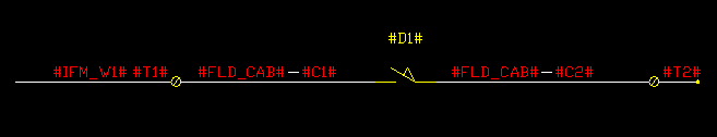
Macro Component "Order"
Macros must contain information which can be used to set the component "order" so that multiple components of the same type, within the macro, can be predictably loaded by the Wizard. To tell the PLC wizard that the first wire name you have assigned is for a particular wire marker symbol, set its WIRENAME attribute to #IFM_W1# or #W1#. Similarly for the second wire to be loaded with data, in the second wire marker symbol, set its WIRENAME attribute to #IFM_W2# or #W2#.
To identify devices use #D1#, #D2#.... inside the TAGNAME attribute.
To identify terminals use #T1#, #T2#.... inside the T1 attribute.
To Identify cable cores [conductors] use #C1#, #C2#.... inside the CORENAME attribute etc.
If you wish to dictate that IO cables on a macro are part of a multi-core cable, continued from the previous IO macro inserted, then set the CABLENAME attribute to #MULTICORE#.
Default Macros supplied
Macros supplied with Elecdes all have the file name MACRO_VPLC_<CODE><M>.DWG or MACRO_HPLC_<CODE><M>.DWG.
The optional M (mirror) character tells the wizard that the symbol is for cards on the right side or lower side of the construction. Cards on the top or the left do not have an M.
The <code> following xxPLC tells the wizard which type of IO channel this symbol represents:
-
DOI = digital output or input
-
AIO = analog output or input
-
PWR = external supply line
-
COM = common leading back to the CARD from a number of Io's
-
GND = an earth
-
SPARE = wiring macro with a spare terminal
-
WEXTN = macro with one or more wire extension markers.
-
The number in the code represents the number of terminals that should be on an attached IO Card symbol; 1,2,3.
You may modify these macros.
USER Macros
Macros made by you must be named as follows: MACRO_VPLC_USER_<yourmacroname>.DWG or MACRO_HPLC_USER_<yourmacroname>.DWG.
The prefix of "MACRO_HPLC_USER_" tells PLC Wizard that it can use this symbol for PLC construction.
The < yourmacroname > code, following the prefix, may be any code you like, however it is suggested that you follow a sensible naming scheme allowing easy selection of your macros.
Macros are not rotated – you must create them in the orientation of final use!