PLC IO Card Catalog Data
PLC IO Cards are added to the catalog using a similar method to device parts. Due to their complex nature they are require a more complex catalog entry than normal Elecdes devices.
Please refer to the procedure for entering device catalog parts (for normal Elecdes devices) for more information on general device catalog entry of part numbers, ratings and dimensions as this information is identical for IO Cards.
We have provided a PLCs subdirectory to contain PLC catalogs (under the IMP_CAT or MET_CAT directory).
In addition to the steps required to add a standard catalog part, PLC IO cards require fields containing configuration data and terminal data for the card.
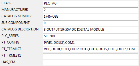
PLC_SERIES
The series number is used to identify a pre-programmed IO channel naming scheme. If PLC wizard recognises the PLC series then it can automatically generate IO addresses for your card.
Use this value to identify the series.
Hint: Supplied catalogs contain all currently available pre-programmed series names.
Example: "PLC5" is a supplied pre programmed addressing scheme for Allen Bradley PLCs.
PT_TERMLIST
The list of terminals on the card, in the order they are to be drawn (top to bottom / left to right).
For numeric terminals you can use a "from-to" series e.g. instead of "2, 3, 4, 5, 6" you could use "2-6".
The maximum width of the field is 255 characters. If this is not large enough to contain your list, you can add a second field named PT_TRMLIST1 and continue adding the terminal numbers in that field.
The terminals must be listed in the correct order according to the "channel" list in PT_CONFIG, described below.
PT_CONFIG
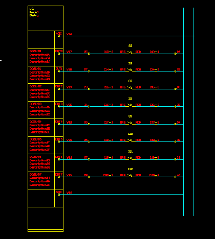
The list of "channels" (and power blocks) on the card in the order they are to be drawn (top to bottom / left to right). Each channel is represented by an IO Card symbol on the drawing and may have 1, 2 or 3 terminals.
The channel name can also be thought of as "the IO card symbol name <code> part". (See above).
I.e. A channel "COM1" will use the IO Card symbol HIPLCCOM1.DWG or VIPLCCOM1.DWG or HIPLCCOM1M.DWG or VPLCCOM1M.DWG, dependent on orientation.
Multiple consecutive channels of the same type can be shown as an "array" e.g. DI1[4] represents an array of 4 consecutive digital inputs, each with 1 terminal.
The channels must be listed in the correct order so that the terminals listed in PT_TERMLIST will match the terminals of the channels. PT_TERMLIST is described above.
The following are channel types:
-
DO1 = digital output
-
DI1= digital input
-
AO1 = analog output
-
AI1= analog input
-
PWR1 = an external supply line
-
COM1 = common leading back to the CARD from a number of Io's
-
GND1 = an earth.
-
The number in each code represents the number of terminals on the channel.
The following shows a card with the configuration : PWR1, DI1[8], COM1
HAS_IFM
Should contain "YES" if the PLC card uses a plug-in Interface Module, or "NO" or empty if the card has its terminals directly on the front of the card. A card with an interface module has only a plug or socket on the front of the card and the interface module provides the terminals.
For cards that have an interface module, the effect in an Elecdes PLC card drawing is to set the terminal numbers of the strip to the terminal names of the PLC card itself, and the wire names to the PLC addresses with a suffix if there is more than one wire per channel.
This changes only how a card appears when drawn in Elecdes. The differences are in the wiring macros.
There is no difference to the components created in Instrument Manager or Cable Scheduler because they do not create the wiring macro components.
CHANNEL
Optional field to set the channel number to be used for naming the Terminal Groups in IM/CS (by default, the CATDESC column is used for naming).
To use this feature, you will have to manually add a CHANNEL column to the catalog file and set the following flag to 1 in the EL32.ini file:
[user-PLCWIZARD]
USE_CHANNEL_FOR_TG_NAME=1
Where "user" in "user-PLCWIZARD" will be your Windows login name.
After adding this field, set it to the starting number that you want your first terminal group to be named as. Other terminal groups will be named as sequential increments of this number.
If the USE_CHANNEL_FOR_TG_NAME flag is set to 1 and the channel field is blank, the starting number for naming terminal groups will be set to 1.