How to Make Electrical Connections Between Components
General
Electrical connections are stored in the project database in the same way as other component links such as containment. Electrical connections are also created in a similar way; by either drag-and-drop or from the "Connect To " item on pop-up menu for a component.
Standard connections between conductors and terminals
It is possible to add a detailed "Wiring Diagram" connection from any terminal, within any Enclosure or Device, to an end of any wire or cable core (conductor) in the IM database. This topic describes the various processes that can be used to make these connections.
The detailed connection will appear in wire and cable core connection reports that are output from IM, wiring diagrams, loops and can be used for installation and maintenance purposes.
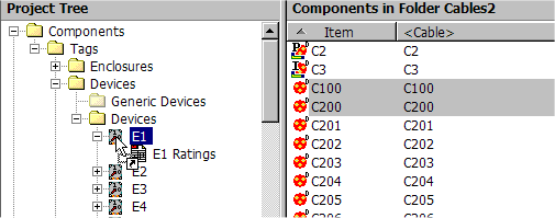
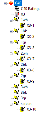
In the category tree, the terminal or cable core (conductor) on an electrical connection will show its parent (e.g. device or cable) and its own name, e.g. E15-3 for terminal 3 of the device E13.
Single Line Cable Connections to Enclosures
It is possible to add a summary "Single Line Diagram" connection to an Enclosure or Device from a Cable.
The summary connection will appear in cable reports that are output from IM and can be used for cable planning and routing.
The methods of connection are identical to those described in the following sections.
The terminations details (individual core or conductor connections) for these cables will not appear on wiring diagrams or core schedules or even in the connection view, as these terminations details are not yet created in any summary connection between Enclosure or Device and a Cable.
If you attempt to connect a cable to an enclosure or device which already contains terminals then you will be required to select its terminations during the connection process.
In the category tree, the cable will appear under the device or enclosure and the device or enclosure will appear under the cable.
Connection Aliases in Lists
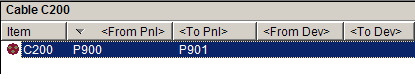
Several alias columns describing detailed and summary connections have been added to IM list views to allow the user to easily identify a conductors connection details ;
-
<From Panel> The Enclosure at the first conductor end.
-
<From Device> The Device/Instrument/Strip at the first conductor end.
-
<From Term> The Terminal at the first conductor end.
-
<To Panel> The Enclosure at the second conductor end.
-
<To Device> The Device/Instrument/Strip at the second conductor end.
-
<To Term> The Terminal at the second conductor end.
These are updated as summary connections or detailed connections are modified. Detailed connections override summary connections. These columns in the list and edit views are normally "read only", you must use the normal connection methods to change these values.
Connection View
Instrument Manager provides a "Connection View" specifically to assist making connections between conductors and components.
The display in connection view is divided into four panes. The top three panes display category trees for equipment, conductors and equipment again, in that order. The bottom pane displays a preview of the connections associated with the component or conductor that is currently selected in the trees above. The divider bars between the panes can be moved to resize your views.
The connection view is designed so that you can use drag and drop operations to make connections between equipment and conductors. You can drag equipment from one of the outer trees onto cables or wires in the centre tree to make a connection. You can also drag conductors in the centre tree to equipment in one of the outer trees to make a connection.
In the graphical preview of the connections in the bottom pane, connections may not show on the sides of terminals that you expect. The connection preview is interpreted by scanning outwards from the component that is currently selected in the trees above. The sides and order of connections are more predictable when devices have appropriate input and output Terminal Groups defined.
Electrical Connection by Drag and Drop
Conductors (wires and cable cores) can only be connected to terminals. Dragging a single conductor onto a terminal will create a single electrical connection. You can make multiple connections in one operation by dragging cables or wires onto devices, terminal strips and instruments that contain terminals. You can make similar bulk connections by dragging cables or wires onto enclosures or areas, which will connect to the components that they contain.
-
Select one cable, core / conductor or wire from the tree, or select multiple conductors from the list in list view.
-
Click the left mouse button over the selected conductor or conductors.
-
Without releasing the left mouse button, drag the mouse pointer to the component to which you wish to connect, then release the button.
Branches of the tree will automatically expand when you move the mouse pointer over them while dragging a selection. The tree will automatically scroll up or down if you move the mouse pointer to the top or bottom of the tree.
-
If you selected multiple cables or wires, then you will be asked if you want to connect all of the cables or wires to the chosen component, or to connect them sequentially to multiple components.
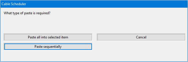
If you choose to connect sequentially, then the first cable or wire will be connected to the component over which you released the mouse button. The second cable or wire will be connected to the next component in the tree, and so on.
If you are pasting sequentially onto child components in an area or enclosure and there are fewer child components in the current area or enclosure than pasted cables, then Instrument Manager will continue sequentially pasting the cables into the next area of enclosure until it runs out of components or cables.
-
You may drag a cable or wire to a container component, such as an enclosure. In this case you will be asked to select one of the components that it contains to which the cable or wire should be connected.
-
If you are connecting a cable, then you can specify the connection on a per-terminal / per-conductor basis. See the description below.
-
If you are connecting a wire then only a single terminal needs to be selected.
-
Click [OK] to make the connection. This will make the links in the database to represent the currently selected connections.
This procedure is repeated for each of the wires or cables that you have selected.
Electrical Connection by selecting "Connect To" from the menu
-
Right click on the component to which you wish to connect a wire or cable.
-
Select "Connect To" from the pop-up menu, then select the type of conductor: either cables or wires.
-
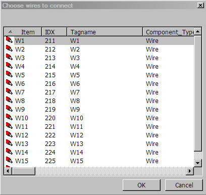
A list of either cables or wires will be displayed. Multiple conductors can be selected from the list.
-
You may have started this operation from a container component, such as an enclosure. In this case you will be asked to select one of the components that it contains to which the cable or wire should be connected.
-
If you are connecting a cable, then you can specify the connection on a per-terminal / per-conductor basis. See the description below.
-
If you are connecting a wire then only a single terminal needs to be selected.
-
Click [OK] to make the connection. This will make the links in the database to represent the currently selected connections.
This procedure is repeated for each of the wires or cables that you have selected.
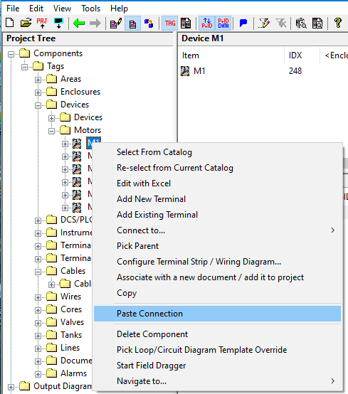
"Copy" and "Paste Connection" from the menu
A component can be connected to another component by copying the component, then pasting a connection to other component. This only applies to wires, cables and cores.
-
Select one component from the tree, or select multiple components from the list in list view that you wish to connect with another component.
-
Right click with the mouse pointer over the selected component or components.
-
Select "Copy" from the pop-up menu or press Ctrl-C.
-
Right click on the component that you want to connect to.
-
Select "Paste Connection" from the pop-up menu or press Ctrl-V.
-
This will set the connection link for each chosen component. The connected components will then be shown as connections in the tree.
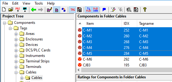
Paste Connection Sequential
Sequential connection allows fast connection of a group of components to another group of components.
For example we can connect five cables to five devices.
-
First copy the five cables into the clipboard.
-
Next choose the first device you wish to connect the first cable to.
-
Choose paste connection and then choose the option. The five devices from the chosen device downwards in the component tree will be connected sequentially to the five cables.
-
For each device you will be able to choose which terminals to connect to which cores.
This can save you a lot of time and effort.
-
Pressing Ctrl-V will also perform this operation.
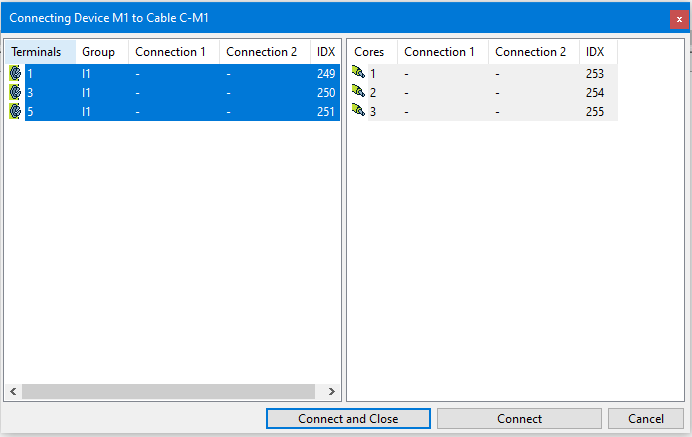
Specifying per-terminal / per-conductor connections for a cable
For either of the procedures described above, If you are connecting a cable then a window is displayed allowing the connection to be specified on a per-terminal / per-conductor basis. In the window there are two lists. On the left is a list of the terminals of the component and on the right is a list of the cores or conductors in the cable.
The Cores list displays any current terminals connected to the cores (at either end). This information is displayed in the columns "Connection 1" and "Connection 2". E.g. If "Connection 1" = "P9:X5:1" then enclosure P9, terminal strip X5 and terminal 1 is connected to the core/wire at end 1.
The Terminals list displays any current conductors connected to the terminals. This information is displayed in the columns "Connection 1" and "Connection 2". The conductor wire-name or cable and core-name are displayed for up to two connections on each terminal.
This list is resizable.
-
Select the terminals that you want to connect in the left list.
-
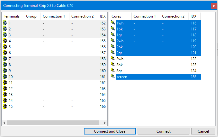
Select the cores or conductors that you want to select in the right list.
-
The connections will be made in the order in which they appear in the lists.
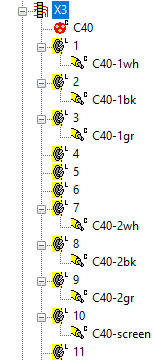
In the example terminals 4, 5 and 6 have been deselected and cores of the third triad are deselected. This configuration will result in the first triad being connected to terminals 1 through 3 and the second triad being connected to terminals 7 through 9. The cable screen will be connected to terminal 10.
The number of connections made will be governed by the list with the least number of selections.
-
If you wish to make the connections in multiple choices, you can click the button. This will make the links in the database to represent the currently selected connections. The function will then reload the lists enabling you to make any remaining connections.
-
When you have chosen the final arrangement of terminals and cores / conductors, you can click the button. This will make the links in the database to represent the currently selected connections.
Disconnection
In the tree view, Instrument Manager offers multiple disconnection options based on the type of component selected, and the number of connections. This makes it easy to fix connection mistakes, without having to interact with multiple items in the tree.
From a master item
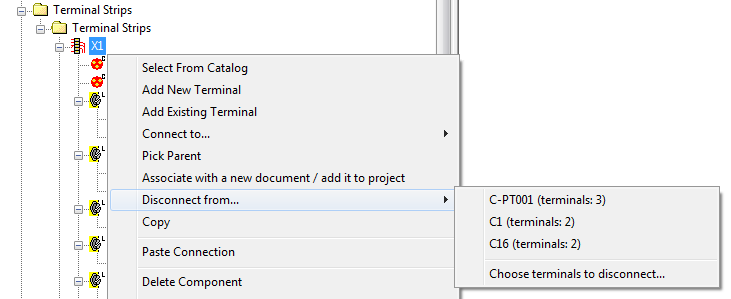
For a master item, such as terminal strip X1 in this image, Instrument Manager will list all connected cables (and specify how many terminals each is connected to). Choosing any one of these will disconnect that cable and all of its cores / conductors from the strip and its terminals.
If the selected item is a cable then the components at each end (if any) will be listed to disconnect.
From a connection shown under a master item
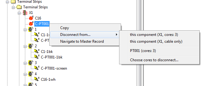
For a connection shown as the child of a master item in the tree, such as cable C-PT001 in this image, Instrument Manager will list all connected components (ie, each end of the cable). Choosing any one of these will disconnect the cable and all of its cores / conductors from that component and its terminals.
If the selected item is a component then all connected cables (if any) will be listed to disconnect.
The first two entries in this context menu are always (or ), meaning the item shown above the selected item in the tree. You can choose to disconnect the component/cable and its terminals/cores, via , or just the component/cable, via .
Other disconnection options
The last option in the context menu, , allows you to choose individual terminals or cores / conductors to disconnect from a pick list dialog.
For individual cable-cores/conductors, wires, and terminals in the tree, only a single disconnection option is given in the context menu. removes the single connection selected in the tree, while removes all connections to the selected conductor/terminal.