How to Represent Multi-tiered Terminals
Fundamentals
Multi-tiered terminals or terminal block terminals need to represented on the project drawings as multiple symbols with distinct (different) names but represent only one part.
This will generate individual entries in the connection reports for each tier/terminal on the part. It will also generate only one entry in the material reports for each part (multiple symbols). This behaviour is different from that for discrete terminals.
Tiers/terminals that are on the part but are not inserted into the project drawings will appear as spare terminals in the wiring diagram system.
Procedure
-
Open the catalog database for the terminal manufacturer (catalog databases can be found in the <EDS>\IMP_CAT (for imperial users) or <EDS>\MET_CAT (for metric users) directories).
-
Create an entry for the part to be represented in the drawings. This information will be used in the material reports.
-
Add a field to the database named "WAYS". This is a special field to indicate that the terminal is a multi-tiered terminal or terminal block.
Fill in the WAYS field for the part with the appropriate configuration value. This value is used to determine the names of the connections represented by the symbols on the drawing. This is required as more than one symbol represents this one part in the drawings.
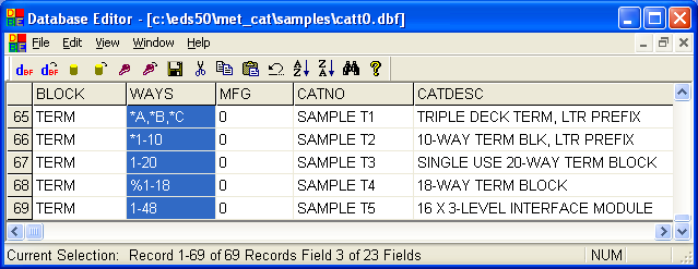
Examples
| WAYS | Terminal names |
|---|---|
| *A,*B,*C | 1A, 1B, 1C, 2A, 2B, 2C, 3A, ... (where '1', '2', '3' can be any number) |
| *1-10 | A1, A2, A3, ..., A10, B1, B2, B3, ..., B10, C1, ... (where 'A', 'B', 'C' can be any letter) |
| 1-20 | 1, 2, 3, ..., 20 |
| %1-18 | 1, 2, 3, 18 or 19, 20, 21, ..., 36 (each group of 18 in this case indicates a separate part) |