How to Mark a Drawing as a Single Line Diagram
General
Single Line Diagrams detail Power Distribution to Medium and High voltage devices, showing device only connectivity.
If single line diagrams will be included in an Elecdes project then the area of each drawing that contains single line symbols should be included in a single line zone, 1LZone.dwg.
Elecdes will not check for terminal level connection information from single line diagrams. Cable connections between devices or panels can be obtained from single line diagrams. The Bill of Materials report will not show duplication warnings where a component is represented by both a single line symbol and a schematic symbol.
Procedure to place a single line zone
-
Select from the menu.
-
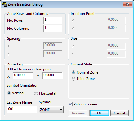
You will be presented with the Zone Insertion Dialog shown below.
-
You must tell Elecdes of the number of rows of Zones required and the number of columns of Zones required.
-
You must tell Elecdes of the size of the Zones required.
-
You must tell Elecdes the position of the Zones required.
-
-
Choose the 1 Line Zone option.

How to
Place an Array of Zones Sized by Picking with the Mouse