How to Draw a Push Button Start-Stop Control Circuit
Fundamentals
This function constructs a push button start-stop circuit with a variable number of start and stop push buttons between two power rails.
Procedure
-
Select Construct PB Start-Stop from the Elecdes > Drawing Macros menu.
-
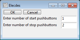
Specify how many buttons of each type are required in your circuit:
Enter the numbers you require then click OK.
-
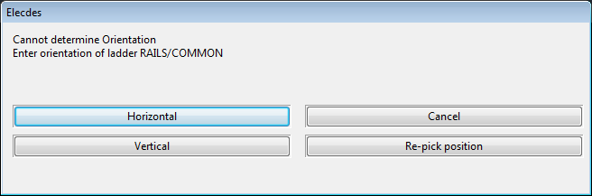
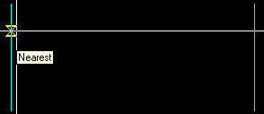
You will be asked to pick the upper/left connection for the start-stop circuit.
If you do not select a LINE for this point, you will be required to enter the orientation of the start-stop circuit you wish to produce.
You should place this connection on the upper/left rail of the power supply rails used to supply this circuit.
-
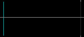
You will be asked to pick the lower/right connection for the start-stop circuit.
The function requires only the vertical/horizontal distance from the upper/left rail.
-
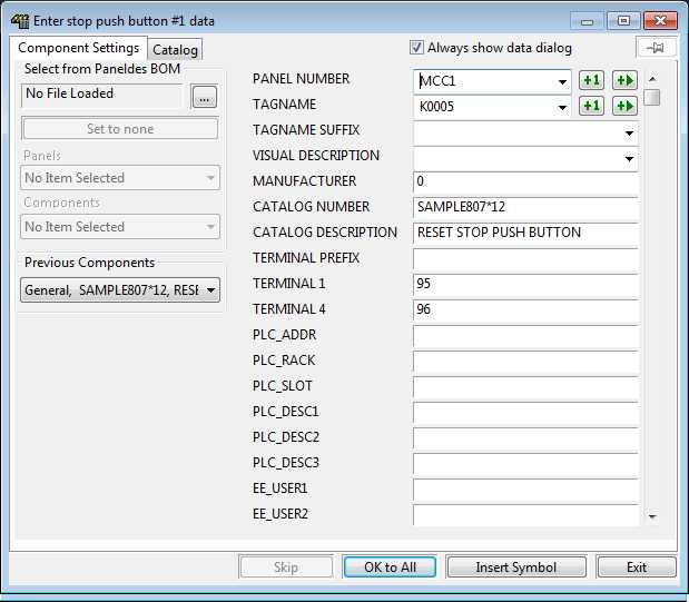
The Elecdes Component Dialog will be displayed allowing you to enter and select attribute data for each stop push button. Refer to the section How to Insert Symbols for more information on entering and selecting attribute data for a component.
The Naming Sequencer will provide you with default values for the naming attributes.
-
Once the stop push buttons are inserted, the Elecdes Component Dialog will be displayed allowing you to enter the data for the contact.
The Naming Sequencer will provide you with default values for the naming attributes.
-
The Elecdes Component Dialog will be displayed allowing you to enter the data for the coil.
The name of the latching contact will be presented as the default for the coil.
-
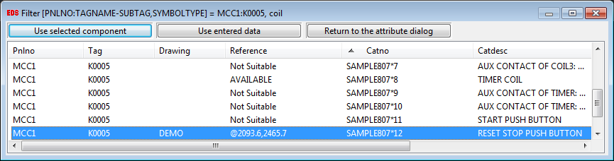
The on-line cross-reference window will be displayed, as the coil is part of the same component as the contact that was inserted previously. The coil subcomponent will be selected by default.
-
For each start push button inserted, you will need to confirm the attribute data of the component within the Elecdes Component Dialog, as required during the standard insertion procedure.
The Naming Sequencer will provide you with default values for the naming attributes.
-
Construction of the circuit will finish.
