How to Generate Terminal Strips From a Database
The Wiring Diagram Generator can obtain the information for generating terminal strips from a database with a particular format, called a Signals file.
Since all of the information is obtained from the Signals file, no schematic drawings or Ebase projects are required.
Procedure to load a signals file
-
Change to the Main dialog of the Wiring Diagram Generator.
-
Click at the top of the wiring diagram dialog box.
A dialog box will be displayed. Generally this dialog is used to select a project file.
-
Click in the Files of type drop down list and change the file type to Signals files (signals*.dbf).
You can select a signals file from any directory.
-
The device list on the wiring diagram dialog box will be loaded with the terminal strips from the signals file.
Contents of a signals file
The signals file has a very regimented structure. The following fields are repeated with increasing numbers replacing the letters "n" and "m".
| Xn | Name of the n'th terminal strip. |
| Xn_T1 or Xn_T2 | Name of a terminal from the n'th terminal strip. Two terminal names are possible. |
| Xn_P | Panel name for the n'th terminal strip. |
| Xn_CATNO | Part number of this terminal from the n'th terminal strip. |
| Xn_MFG | Manufacturer code of this terminal from the n'th terminal strip. |
| C_n_m | Name of the cable connected from the n'th terminal strip to the m'th terminal strip. |
| W_n_m | Name of the core (conductor) of the cable, or the name of the wire connected from this terminal on the n'th terminal strip to the m'th terminal strip. |
Not all of the fields are required. You will require at least a terminal strip name, a terminal name and a wire or core (conductor) name to generate a wiring diagram.
Signals file example
The following is an excerpt from a signals database.
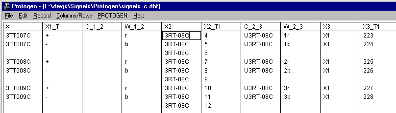
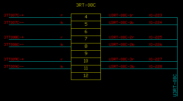
The data in the example file can generate the following terminal strip diagram for the terminal strip named 3RT-08C.
-
Column X2 provides the name of the terminal strip in the example below.
-
Column X2_T1 provides each terminal number for the terminal strip 3RT-08C.
-
Column X1 provides the name of the terminal strip to the left of 3RT-08C.
-
Column W_1_2 provides the name of each wire connected between the terminal strip in column X1 to the terminal strip in column X2, the strip in the example below.
-
Column C_1_2 is blank because wires (as opposed to cables) are used to connect the terminal strip in column X1 to the terminal strip in column X2.
-
Similarly on the other side of the strip:
-
Column X3 provides the name of the terminal strip to the right of 3RT-08C.
-
Column C_2_3 provides the name of the cable connecting the terminal strip in column X2 to the terminal strip in column X3. Column W_2_3 provides the core (conductor) names for that cable.