Size and Scale of a Device Wiring Diagram
Size and Scale of Devices
The settings in the Device Sizing group enable you to control the size of the body of the device in the wiring diagram for each of the devices. These are parametric sizes. If you change the values, the wiring diagrams will change in size.
The settings will apply to all of the devices that will be drawn when you create the wiring diagram.
The settings should be in drawing units.
Default device width - dimension E
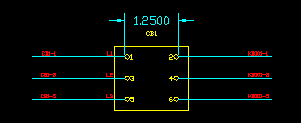
The default device width refers to the distance between the two columns of terminals on each side of a wiring diagram. It is used to position terminals when physical (CATX) or MTD terminal layouts are not used.
Minimum terminal spacing - dimension F
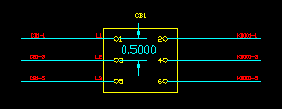
This setting is used to ensure that terminals and conductor lines extending from terminals are sufficiently spaced to avoid two terminals overlapping.
If a terminal is within the specified minimum terminal spacing of another terminal, the interfering terminal will be offset to the minimum terminal spacing from the other terminal.
This offset rule applies to all terminals including the physical (CatX) or MTD terminal layout options. Therefore, the terminal layout may not exactly match the physical or MTD layout of the device.
If terminals must be offset, the height of the body of the device will be extended to encompass the modified terminal layout. If a circle represents the body of the device, the circle will not be altered.
Terminal margin - dimension G

The terminal margin specifies the distance between the terminals and the rectangle or circle representing the body or outline of the device.
This setting is used when the body of the device is calculated to fit a given terminal arrangement
Scaling of physical dimensions
When the terminal arrangement has been obtained from the terminals catalog [ CATX ], the terminal positions are specified in physical units. Device dimensions are given in physical units in the device catalogs [ CATD ]. See Sources of information for Wiring Diagrams.
Set the scaling parameter to represent these sizes on your wiring diagram.
In the example, 12 drawing units equals 1ft. This means each drawing unit will represent one inch when physical units are used for drawing the wiring diagram for a device.
If you are using the metric measurement system, you must set the number of drawing units that equals one metre.
These settings can be found on the Devices tab page of the wiring diagram settings dialog.