How to Change Class Layer Assignment
General
Paneldes allows you to assign a construction layer to any Paneldes LAYER CLASS. A Paneldes layer class is a group of related Paneldes classes. Paneldes layer class groups are detailed below.
The layers you wish to use are listed in a file named LAYER.DBF. The file contains the details needed to create a layer and link it to a Paneldes layer class. Any layer linked to a Paneldes layer class will cause all components constructed, which are of that layer class, to be placed on the linked layer.
You may create layers, which are not linked to a Paneldes layer CLASS, with LAYER.DBF.
Paneldes will create any layers (not currently in existence on your drawing) listed in LAYER.DBF at start-up.
The layers that you require in your model will all be present when you start construction.
Layer Classes
| Layer Class | Paneldes classes (CAPS) / or other construction. |
|---|---|
| Routes | All route lines. |
| Panel_frame | PANEL. |
| Mounting_plate | MOUNT. |
| Accessory | ACCESSORY. |
| Device | DEVICE, INSTR. |
| Screw | SCREW. |
| Construction | 3D envelope construction for ROUTE's (e.g. DUCT, CABTRAY, CONDUIT). |
| Extras | EXTRAS (invisible accessories). |
| Border | Border insertion layer. |
| Routedisplay | Layer "routedisp"; for viewing cable/wire routes |
| Area | AREA |
| Terminals | TERM |
| Routes_Dims | Dimensions for route lines |
| Panel_Frame_Dims | Dimensions for panel frames |
| Mounting_plate_dims | Dimensions for mounting plates |
| Device_Dims | Dimensions for devices |
| Accessory_Dims | Dimensions for accessories |
| Screw_Dims | Dimensions for screws |
| Construction_dims | Dimensions for construction |
| Extras_dims | Dimensions for extras |
| Areas_Dims | Dimensions for areas |
| Terminals_Dims | Dimensions for terminals |
| Routes_Blocks | 3D blocks for routes |
| Panel_Frame_Blocks | 3D blocks for panel frames |
| Mounting_Plate_Blocks | 3D blocks for mounting plates |
| Device_Blocks | 3D blocks for devices |
| Accessory_Blocks | 3D blocks for accessories |
| Screw_Blocks | 3D blocks for screws |
| Construction_Blocks | 3D blocks for construction |
| Extras_Blocks | 3D blocks for extras |
| Areas_Blocks | 3D blocks for areas |
| Terminals_Blocks | 3D blocks for terminals |
| Vports | View ports |
| TextImport | Text Importing |
| ScrewCentres | Dimensions for screw centres |
| Centres | Dimensions for centres of all other components |
Modification of Layer Settings
You may modify the layers available in your drawing and their links to Paneldes CLASSES by editing the file LAYER.DBF with a database editor such as Dbedit. This file may be found in the main Paneldes directory.
Note: You must edit the layer.dbf file before you start Paneldes. Changes in this file are only recognised at Paneldes start up.
A editing session on LAYER.DBF will appear as follows:
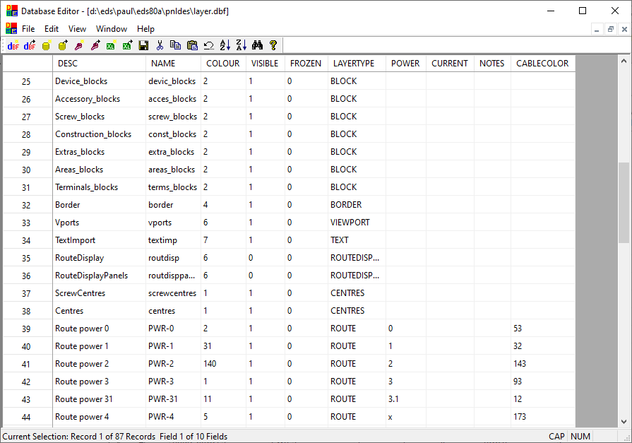
-
DESC names the layer class.
-
NAME assigns a layer name to the layer class. You may place any name you wish in this column. This will be the layer name AutoCAD will give to a layer created.
-
COLOUR names the layer color.
-
VISIBLE sets the layer visibility ON or OFF at start up.
-
FROZEN sets if the layer is frozen ON or OFF at start up.
-
LAYERTYPE sets the layer type. The values in this column are not used except for layers associated with a specific power factor. For layers of this type the value indicates if it is for route lines (ROUTE) or route envelope lines (CONST).
-
POWER specifies the power factor for the layer.
-
CURRENT selects one layer as the current layer at start up.
-
CABLECOLOR names the color to use for drawing viewed cables with this power number when the option Use power-based colours is enabled.
-
TRANSPRNCY specifies the transparency level for the layer, as a percentage value between 0 and 90, where 0 (or blank) is fully opaque, and 90 is almost completely transparent (AutoCAD does not support transparencies above 90%).