How to Draw a Cable as a Single Line
Fundamentals
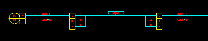
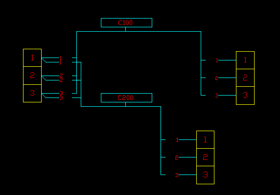
The Polyline Cable Function is provided to create a set of lines and polylines, which represent a cables, linking two or more sets of terminals. The cables are drawn as polylines. Each end of the cable is "broken out" into individual cores(conductors) of that cable.
Up to 3 separate polyline cables can be attached to a single terminal.
Example:
Conductor Lines
The lines representing individual cores(conductors) are constructed as regular line segments and hence will be recognised during interconnection analysis. The polyline representing the cable is purely for graphical information. It is not recognised during the interconnection analysis.
Please also review Conductor Array Construction for more information on Elecdes' interpretation of line segments and polylines for interconnection.
Refer to the Ebase for more information on interconnection.
Cable core(conductor) marker
A cable core marker is inserted upon each of the cable core(conductor) lines and another showing the cable name.
Elecdes has modified cable core(conductor) markers for the construction of this circuit. They are named VCCABLEL3, VCCABLER3, VCCABLE4 and VCEXTN9. These have modified cablename and corename attributes (visibility and justification modifications). They contain the same information as a regular cable core(conductor) marker, just modified in appearance to suit the polyline cable circuit.
Terminals
Any terminals may be selected for the two terminating ends of the cable. The function will detect the size of the terminals selected and align the connecting wires appropriately.
Procedure
-
Select from the menu.
-
You will be asked to select the terminals for the first end of the cable. You should select the leftmost column or uppermost row of terminals.
The selected terminals do not have to be aligned with each other. The function will use connecting lines of appropriate lengths to connect each terminal to the cable polyline.
Press <ENTER> when you have finished selecting the first group of terminals.
-
You will be asked to select the terminals for the other end of the cable. You should select the rightmost column or lowermost row of terminals.
Press <ENTER> when you have finished selecting the second group of terminals.
If you are creating a single sided polyline cable then just press <ENTER> without selecting any terminals for the second group.
-
You will be asked to pick the position of the cable marker. Pick a point suitably in the centre area between the two groups of terminals, otherwise the lines will cross each other.
If you are drawing a single sided polyline cable then you can choose a point to either side of the group of terminals that allows space for the lines.
-
The Elecdes Component Dialog will be displayed allowing you to enter and select attribute data for the cable. Refer to the section How to Insert Symbols for more information on entering and selecting attribute data for a component.
The Naming Sequencer will provide you with default values for the naming attributes.
-
The polyline for the cable will be drawn and the cable marker will be inserted onto the polyline. The polyline will not be processed by the interconnection analysis. The first cable core (conductor) line segment will be drawn linking the top-left terminal to the cable polyline. The core (conductor) line is a regular line segment, which will be processed normally by the interconnection analysis.
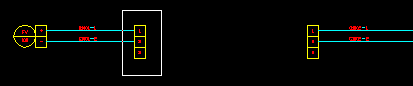
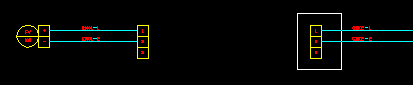
If you are drawing a single sided polyline cable then a cable extension marker is inserted for the cable, which means that it will be cross-referenced to the other end when that is drawn.
If there is already another polyline cable attached to the same side of the same terminals then the lines and polylines of the new polyline cable that you are inserting will be offset to avoid drawing over the lines and polylines of the existing drawing.
-
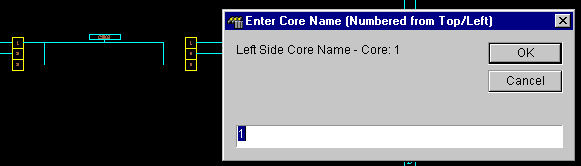
A dialog box will be displayed for you to enter the name of the cable core (conductor) connected to the top-left terminal.
The Naming Sequencer will provide you with default values for the naming attributes.
-
The dialog will be re-displayed to confirm each of the cores (conductors) on the first side of the cable. Each core name will be incremented as specified by the Naming Sequencer.
-
The dialog will be re-displayed to confirm each of the cores (conductors) on the second side of the cable. The core (conductor) name will be re-set to the first value for the first cable core (conductor) line linking the cable polyline to the right or bottom set of terminals.
Each core (conductor) name will be incremented as specified by the Naming Sequencer.
-
Construction of the polyline cable will finish.