How to Manually Name Conductors in a Drawing
Fundamentals
Elecdes has two types of conductors that can be represented on the electrical drawings. Panel wires and cable cores.
Different blocks are used to represent the two different types of conductors, and these different types of conductors will appear in separate reports. The main difference in the blocks for cable cores and panel wires are the attributes used to name the conductors.
Panel Wire
A panel wire is intended to represent the wiring inside a panel, where each conductor on the drawing marked as a panel wire can represent an individual wire / conductor / single core cable or bus bar. The name of the conductor is defined by the value in the WIRENAME attribute.
Cable Core
A cable core represents a single core (conductor) within a multi-core cable. The name of the conductor is made up of two parts, the CABLENAME attribute contains the name of the cable which contains the core, and the CORENAME attribute identifies the core within the cable.
Procedure
Panel Wire
-
Select from the menu.
-
There are two types of wire makers by default. The inline marker and the wire leader marker. In the Place panel wire number function you can insert either of these. The inline marker is the default.
To insert the leader symbol you can use the [Leader] option in the AutoCAD command line. Typing L <ENTER> in the command line will toggle it to leader insertion mode.
When in leader mode you can use the [Inline] option, by entering I <ENTER> in the command line, to toggle back to inline wire markers.
-
Choose the locations at which to insert the marker symbols. This should be on the line segment used to represent the conductor. You can also insert multiple markers in one step, or arrays of markers. See the Multiple insertion section for more details.
If you pick a point that is not on a line segment, then this will begin the automatic wire insertion function. If you simply missed the line, then you can press <ESC> to cancel that function.
-
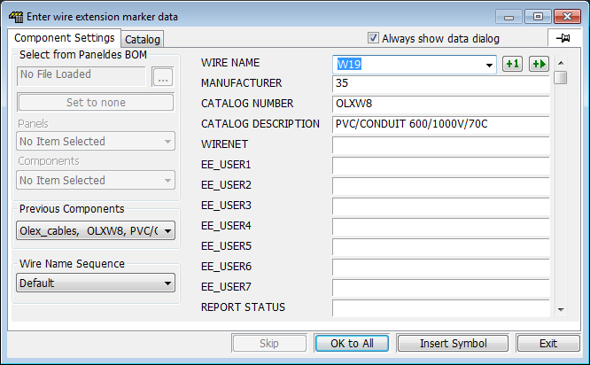
For each wire marker you will need to enter the attribute data into the Elecdes Component Dialog, the same as required during the standard insertion procedure. The name of the wire will be incremented in the sequence configured by the Naming Sequencer.
-
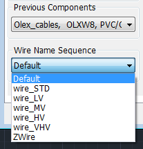
Wire markers can have a variety of naming styles. You can choose one of the available name sequences from a drop-down list in the bottom left corner under the selection of previous components. Choosing a new sequence from this list will re-set the wirename attribute on the right side of the dialog to next value in the chosen sequence. This choice is linked to the same choice in the Elecdes preferences. See How to Configure Cable and Wire Naming Sequences.
The choice of "Default" will let the EDS Name Sequencer make its automatic choice of sequence based on the parameters available, e.g. zone, page, layer or line layer.
The Naming Sequencer can build your tagnames using the following drawing based data; the name of a ZONE to which you inserted the symbol, the name of the current LAYER, the name of the layer of the line (LINELAYER) you inserted on to, the sheet name or PAGE you have entered in your titleblock. In "Modeless" mode the dialog can live update the tagname as you roll your mouse over different ZONES and LINES if you activate the [Zonetag] command line option (press Z then <enter>).
-
When you are satisfied with the data in the Component Dialog for the first wire, click the Insert Symbol button.
-
The function will continue to run, allowing the placement of as many wire markers as required. Press the ESCAPE key to exist.
Cable Core
-
Select from the menu.
-
Choose the locations at which to insert the marker symbols. This should be on the line segment used to represent the conductor. You can also insert multiple markers in one step, or arrays of markers. See the Multiple insertion section for more details.
-
For each core marker you will need to enter the attribute data into the Elecdes Component Dialog, the same as required during the standard insertion procedure. The name of the cable will be incremented in the sequence configured by the Naming Sequencer.
-
You can link a particular cable catalog entry to a specific name sequence for the cores via the NSQ_KEY field of the catalog record. Into the NSQ_KEY field enter the attribute name followed by an '=' sign followed by the unique key for the sequence. For example, if the NSQ_KEY field in the catalog entry for a cable contained "corename=COLORS_Core" then the cores of that cable would be named by the sequence with the key "COLORS_Core".
-
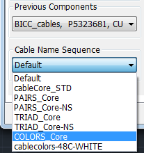
Cable core (conductor) markers can have a variety of naming styles. You can choose one of the available name sequences from a drop-down list in the bottom left corner under the selection of previous components. Choosing a new sequence from this list will re-set the core (conductor) name attribute on the right side of the dialog to next value in the chosen sequence. This choice is linked to the same choice in the Elecdes preferences. See How to Configure Cable and Wire Naming Sequences.
The choice of "Default" will let the EDS Name Sequencer make its automatic choice of sequence based on the parameters available, e.g. core or conductor configuration.
-
When you are satisfied with the data in the Component Dialog for the first core, click the Insert Symbol button.
-
The function will continue to run, allowing the placement of as many core markers as required. Press the ESCAPE key to exit.