How to Draw a 3 Phase Circuit
Fundamentals
This function constructs a 3-line circuit in any ORTHOGONAL direction and allows periodic selection of components and conductor markers to include on the 3 lines.
The purpose of this function is to avoid the time consuming line construction and device positioning PICKS necessary in manual 3-phase circuit construction.
During construction of the circuit you may override the auto spacing settings and construct corners in any ORTHOGONAL direction.
Procedure
Starting 3 Phase Autodraw
-
If you wish to draw a normal 10mm or 3/8in spaced three phase circuit select Construct 3 phase cct from the Elecdes > Drawing Macros menu. Alternatively if you wish to draw a 15mm or 1/2in spaced three phase circuit select Construct 3 phase cct with 15mm or 1/2in spacing from the Elecdes > Drawing Macros menu.
-
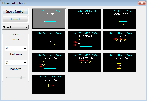
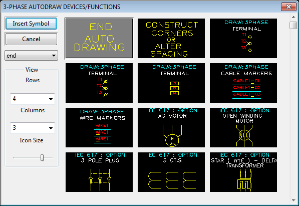
The START METHOD icon menu will be displayed.
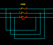
Select a start method (3 terminals, 45 degree connection, bare lines) AND the initial orientation of the first three lines in the circuit, by clicking on the desired icon.
-
Elecdes will now know the desired appearance of the start of the circuit and request the start point for the CENTRE of the 3 lines.
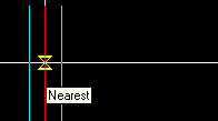
Pick the start point of the circuit. If a 45-degree connection has been chosen, OSNAP will be set to nearest, to aid in the selection of the centre line of the circuit you wish to connect to.
-
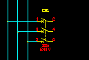
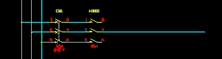
OPTION - If you have chosen to include terminals at the start of the circuit you will now be asked to provide attribute data for the first (upper or leftmost) of the three terminals.
For each symbol you will need to confirm the data of the component within the Elecdes Component Dialog, as required during the standard insertion procedure. The name of the terminal will be incremented in the sequence configured by the Naming Sequencer.

-
Any terminals will now be inserted and the COMPONENT SELECTION icon menu will be displayed.
The component icon menu contains a variety of options for the "next item" in the circuit.
Select the option desired by clicking on the desired icon.
-
Selections from this menu may be repeated until you wish to END the construction. See below for the END and other "next item" options.
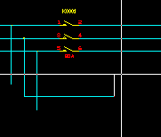
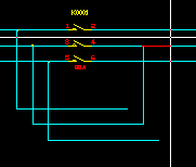
Construct Corners or Alter Spacing
-
This option allows you to construct 1 or multiple sections of 3 lines by drawing in the centre line only. These lines may be in any direction. Pick the next point of the centre line until completed, then press <ENTER> to return to the component selection icon menu.

-
Once ENTER is pressed you will be returned to the component selection icon menu.
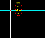
For example:


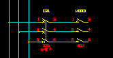
Select 3-phase device OR 3 single-phase devices
-
At any point during the 3-phase circuit macro, you can choose devices, terminals, wire markers or conductor markers to be the "next item" inserted to your circuit. Click on the desired icon. Elecdes will draw the three connecting lines if required.
-
The Elecdes Component Dialog will be displayed allowing you to enter and select data for the component's attributes. Refer to the section How to Insert Symbols for more information on entering and selecting data for a component's attributes.
-
The component selection icon menu will be re-displayed allowing you to select the next item.

END Auto Drawing
-
Select this option to end the circuit. You may end the circuit with terminals, a 3-phase connection or bare lines.
-
Elecdes may request the end point for the CENTRE of the 3 final lines.
You will not be asked for the last point if you have just completed Constructing Corners / Altering Spacing.
You will be asked for the last point if you have just inserted a symbol or symbols.
-
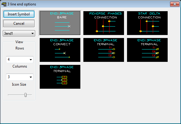
The END METHOD icon menu will be displayed.
Select an end method (3 terminals, 45 degree connections, bare lines), by clicking on the desired icon.
-
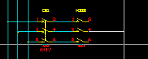
If you have chosen to include terminals at the end of the circuit, then you will now be asked to provide attribute data for the first (upper or leftmost) of the three terminals.
For each symbol you will need to confirm the attribute data for the component in the Elecdes Component Dialog, as required during the standard insertion procedure. The name of the terminal will be incremented in the sequence configured by the Naming Sequencer.
-
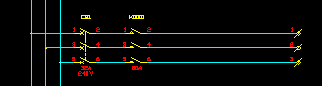
The lines will be constructed, selected symbol(s) inserted and the function terminated.
Examples of usage:
-
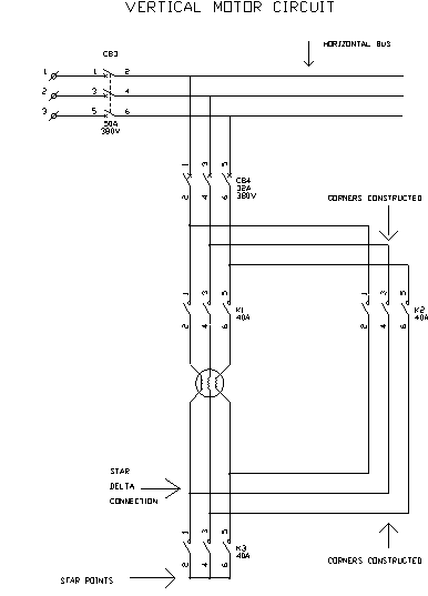
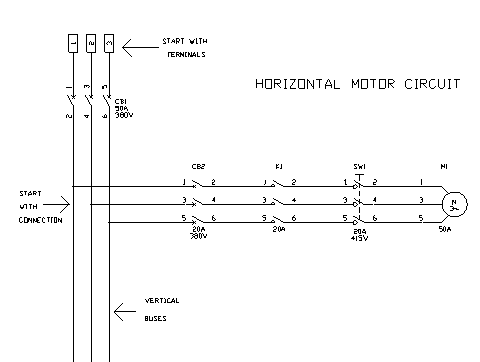
3 phase motor circuits (with reversing or star (wye) - delta start)
-
Supply bus circuit and redundancy links.