How to Configure Drawing Layers
The Elecdes layer definitions are stored in a text file called Layer.ref, which is located in the <EDS>\ELECDES sub directory.
Layer.ref provides a place to specify all of the layers that will be created to prepare for drawing in any drawing that you open or create with Elecdes. There are other layers that exist only in the symbols and other blocks. These are created in your drawings when you insert those block files.
The layer definitions are used for a variety of purposes. These layers and their respective uses are outlined below.
Special Purpose Layers
| Layer Name | Description |
|---|---|
| "Xref" and "Xrefinv" |
These layers are reserved for cross-referencing symbols and text. During a symbol cross-reference operation all of the entities on these layers are erased. You should not use these layers for general drawing. |
| "Xref_Layer" |
Each cross-reference symbol contains a surrounding box that is drawn on this hidden layer for alignment when modifying these symbols. This layer is defined only in the cross-reference symbols (not layer.ref) and is not essential. |
| "Taglayer" |
All naming attributes (TAGNAME, CABLENAME etc.) are placed on this layer, allowing individual control of colours etc. This layer is also defined in the symbol files and will be added to drawings upon insertion. |
| "Etext" |
All other attributes (terminal numbers, ratings etc.) are placed on this layer, allowing individual control of colours etc. This layer is also defined in the symbol files and will be added to drawings upon insertion. |
| "Worder" |
Termination blocks, which should generally remain invisible, are placed upon this layer, which is a frozen layer. |
| "Ferrule" |
The FERRULE attribute of the termination (CONX) blocks has been created on this visible layer, distinct from the other attributes of the termination block which are generally invisible. This layer is defined only in the termination blocks (not layer.ref) and is not essential. |
| "Dotbox" |
This layer has been specifically created for the use of the Elecdes Dotted Box command. The dotted box command creates a rectangular polyline on this layer. The layer has a dashed line type EDS_DASHED which can be customised. The EDS_DASHED line type is found in the <EDS>\ELECDES directory as EDSMET.LIN or EDSIMP.LIN for metric and imperial respectively. |
| "LineBreak" |
This layer is used to contain a hidden segment of a conductor line when the wire crossing style is chosen such that a gap will be left in one of the lines. There is not really a gap - there is simply a small arc that is hidden. |
| "TableConf" |
This hidden layer is used to contain the attributes of the Column Header, (IMPCOL) blocks that contain the configuration for a DBF file imported to a drawing. This layer is defined only in the IMPCOL blocks (not layer.ref) and is not essential. |
| "Form1" and "Form2" |
The Australian Standard AS1102 device symbols contain two forms for representing a switch or contact. You can switch between them by showing your choice of the Form1 or Form2 layer. These layers are defined only in the AS1102 standard symbols (not layer.ref) and are not essential. |
| "1".. "4" |
These layers are provided as examples of general drawing layers. You may use these layers to insert symbols, lines and text as you wish. |
Customisation
You can add your own layers, or modify the colours and line types of the existing Elecdes layers by editing the Layer.ref file in the ELECDES sub directory.
You may also remove layers from layer.ref or remove the layer.ref file entirely. If you remove all of the layer definitions or remove the layer.ref file the Elecdes will not create any layers in drawings that you open or create. In the absence of a definition for an essential layer, Elecdes can still create the layer if required using the default parameters.
The following picture shows the structure of the layer.ref file
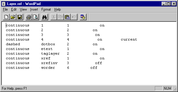
The first column is the line type, followed by the name, followed by the colour number and finally the initial state of the layer. To make a layer the current layer include the word "current" at the end as in layer 4 above.
Dual Layering System
To provide clarity of drawings, during drawing creation and editing, Elecdes has a dual layering system.
This system allows you to choose any layer on which to place Elecdes symbols, whilst drawing all other items on a separate layer (the current layer).
This is achieved by selecting the desired current layer in your CAD package, (start-up default is layer "4") AND selecting the Elecdes "symbol layer" (start-up default is layer "2" set with Elecdes Preferences see Changing the Symbol Layer).
Once these two layers are set, Elecdes will automatically place symbols, inserted from the Elecdes toolbars, on the symbol layer whilst leaving the current layer set for other drawing.
You may disable the dual layering system in the Elecdes Preferences