Symbol Customisation for 2D Panel Layouts
General
Elecdes uses Dynamic Blocks for inserting 2D Panel layout components. BricsCAD users have the alternative option of using Parametric Blocks, a feature that is also supported by Elecdes and Ebase. These blocks can have different views of a schematic components in the single symbol file resulting in fewer block files and complicated file naming. The Elecdes installation is provided with sample block filess which can be used for 2D Panel layout symbol insertion. The sample 2D blocks have one or more of the following views by default:
| FrontView | Component viewed from the front side. |
| BackView | Component viewed from the back side. |
| LeftView | Component viewed from the left side. |
| RightView | Component viewed from the right side. |
| TopView | Component viewed from the top looking downwards. |
| BottomView | Component viewed from the bottom looking upwards. |
Notes for all 2D Panel Layout component symbols
There is no need to have an "h" version for your 2D Panel Layout symbols. The "v" orientation is sufficient and is required to match the Elecdes symbol naming pattern.
All 2D Panel Layout symbols must have "P2D" in their file name after the orientation and symbol type character, i.e. viP2D*.dwg, vtP2D*.dwg
All 2D Panel Layout Symbols must not have LENGTH attribute in them.
All 2D Panel Layout Symbols must have BUSW code set to 888.
All 2D Panel Layout Symbols must set the BLOCK2D column in their respective catalog entry to be able to be used for insertion in Elecdes.
User-customised versions of 2D Panel Layout Symbols can be placed in the <EDS>USER_SYMB directory. EDS will always check the <EDS>USER_SYMB directory for any symbol before checking it's default directories.
Procedure
Creating a New 2D Symbol or Altering the Appearance of an Existing 2D Symbol
Dynamic Blocks (AutoCAD)
Run a CAD session.
To create a new 2D symbol we recommend copying one of 2D blocks from the Elecdes library and modifying it according to your requirements.
To alter an existing 2D symbol:
Load the symbol with the "OPEN" command from the appropriate directory.
If you are using AutoCAD then you will be presented with a dialog shown below with the symbol name to be edited.
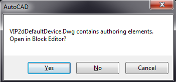
Click on Yes and the symbol will be opened in the block editor. If you are using the standalone version of Elecdes then you may have to manually open the symbol file in block editor.
Edit the graphical part of the symbol to your new, desired appearance (lines, arcs, etc.). If major changes are made to the graphical appearance of the symbol, ensure the insertion point of the symbol remains unchanged.
For adding another view to the symbol double click on the Visibility parameter named Visibility1 as shown in the figure below.
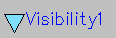
NOTE: Do not change the name of the visibility parameter as Elecdes accepts a visibility parameter with the name Visibility1 only.
You will be presented with a dialog showing all the visibility states of the selected block
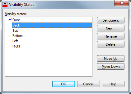
To start editing a view you can press Set Current and then press OK
You can also rename, delete move up and down the selected view in the selected block.
For adding a new view press New button. You will be presented with a dialog to add a new visibility state to your symbol
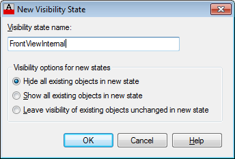
You can choose the name of your new view and select the visibility options for your new state and click OK.
You will be presented with a blank sheet where you can draw your chosen view on the drawing and save the file.
When you are trying to insert your symbol using the insert 2D Panel Layout Components menu. You will be presented with the newly created view in the view list.
Parametric Blocks (BricsCAD)
Run a BricsCAD session.
Open the Visibility States Panel using the VISIBILITYSTATES command OR click on the Visibility icon in the Parametric Ribbon panel.
If you are creating a new parametric block, add a new visibility parameter named Visibility1. NOTE: Elecdes accepts a visibility parameter with the name Visibility1 only.

Use the Add State button in the Visibility States Panel to add new visibility states to the parameter. You can also rename or delete any existing visibility states here.

To add entities to a visibility state:
Open the visibility state using the > button.
Click on the + button.

Select the entities in the drawing that you wish to add to the selected visibility state.
Symbol File names
The file/block names for 2D Panels, Devices, Plates and Accessories begin with a prefix of "VI" followed by "P2D" followed by schematic file name.
The file/block names for 2D Terminals begin with a prefix of "VT" followed by "P2D" followed by schematic file name.
The file/block names for 2D Bar links begin with a prefix of "VW" followed by "P2D" followed by schematic file name.
"P2D" identifies a dynamic block used for Elecdes drawings.
"I" in the block name identifies it's a 2D Panel or 2D Device or 2D Plate or a 2D Accessory.
"T" in the block name name identifies its a 2D terminal.
"W" in the block name name identifies its a 2D bar link.
e.g. "VIP2DFU.dwg" for a 2D representation of fuse.
e.g. "VTP2DTerm1.dwg" for a 2D representation of a terminal.
e.g. VWP2DBAR1.dwg" for a 2D representation of a bar link.
Saving the block file as a 2D block
If you have created a 2D device, panel, accessory or a plate then you should add "VIP2D" in front of your dynamic block file name.
If you have created a 2D Terminal then you should add "VTP2D" in front of your dynamic block file name.
If you have created a 2D Bar conductor you should add "VIP2D" in front of your dynamic block file name.
Catalog Entry
If you have created a new block file then you need to create a catalog entry for the newly created block.
Please remember to put the file name of the 2D blocks after removing the first two letters in to the BLOCK2D column of your catalog entry. e.g. If the new 2D block was named "VIP2DPANEL_80.DWG" then "P2DPANEL_80" should be put in to the BLOCK2D column of the catalog.
Here is a list of catalog files you need to edit depending upon the type of component you have created.
CatgX.dbf Catalog entries for 2D Panels, plates and Accessories CatdX.dbf Catalog entries for 2D Devices CattX.dbf Catalog entries for 2D Terminals CatwX.dbf Catalog entries for 2D Bar Conductors If you edited or altered an existing 2D block then there is no need to edit the catalog file.
For more information about Elecdes catalog files click here.
Directory
Once the dynamic block is created save it in <EDS>\USER_SYMB directory of your Elecdes installation.
Here is how you should name your 2D blocks.
For 2D Panels, Device, Plate and Accessory blocks use VIP2D followed by the block name. e.g VIP2DPANEL_001.dwg
For 2D Terminals blocks name prefix VTP2D followed by the block name. e.g VTP2DTERM_001.dwg
For 2D Bar Conductors blocks name prefix VWP2Dfollowed by the block name. e.g VWP2DBARLINK_001.dwg
Adding Attributes to Component Symbols
You can add attributes to existing or newly created 2D Blocks. Go though the following steps while adding attributes
Dynamic Blocks (AutoCAD)
Run the CAD and open the 2D block in Block Editor
Double click on Visibility1 parameter and select the visibility state to add the attribute to.
Note: Default Elecdes attributes should always be added to the first visibility state. Custom attributes may be added to any state, see Dynamic Blocks.
Click on Define Attributes button on the menu.
You will be presented with the Attribute definition window. Fill in the tag prompt etc.
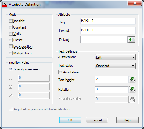
If the attribute is a default Elecdes attribute, uncheck the checkbox.
For custom attributes, see Dynamic Blocks for the affects of locking/unlocking attributes.
Note: Do not define any attribute named LENGTH in a 2D block
Click OK to add the attribute.
Parametric Blocks (BricsCAD)
Run the CAD session and open the 2D block drawing.
Open the Define Attributes dialog using the ATTDEF command or by clicking on the Define Attributes button in the Insert ribbon panel.

Fill in the tag, prompt, etc. properties and click OK.
If you want the attribute to show only in a specific visibility state, follow these steps:
Open the Visibility States Panel using the VISIBILITYSTATES command OR by clicking on the Visibility icon in the Parametric Ribbon panel.
Open the visibility state using the > button.
Click on the + button.
Select the attribute in the drawing to add it to the selected visibility state.
Attributes that are not added to any visibility states will appear in all visibility states. Default Elecdes attributes should not be added to any visibility states.
Default attributes of 2D Panel Layout symbols
The supplied panel symbols have the set of attributes shown below.
Note: "Catalog" indicates an attribute can be loaded from the catalog.
Attributes for 2D Devices, 2D Panels, 2D Plates and 2D Accessories
Here is the list of default attributes for 2D Devices,2D Panels, 2D Plates and 2D Accessories.
| Attribute | Visibility | Catalog | Description |
|---|---|---|---|
| TAGNAME | Visible | Tag of 2D component | |
| PNLNO | Invisible | Panel name | |
| RATING1 | Visible | Yes | User specified rating |
| RATING2 | Visible | Yes | User specified rating |
| RATING3 | Visible | Yes | User specified rating |
| RATING4 | Visible | Yes | User specified rating |
| REFERENCE | Visible | Cross reference data is automatically loaded to this attribute. | |
| CATDESC | Invisible | Yes | Catalog description of component (e.g. "MCC cubicle") |
| VISDESC | Visible | Users visible description of component. (e.g. "conveyor drive") | |
| MFG | Invisible | Yes | Manufacturer code number ( from manufact.dbf ) |
| CATNO | Invisible | Yes | Manufacturers part number |
| USER_C1 | Visible | Yes | User definable attribute, centre justified |
| USER_C2 | Visible | User definable attribute, centre justified | |
| RSTATUS | Invisible | Yes | Control code for the "report status" e.g. Set to "No BOM" to exclude from the materials reports |
| VSN | Invisible | (Constant) Version number, for internal use only | |
| BUSW | Invisible | (Constant) The BUSW value for all the 2D Symbols is "888" |
Attributes for 2D Terminals
Here is the list of default attributes for 2D Terminals.
| Attribute | Visibility | Catalog | Description |
|---|---|---|---|
| TBLOCK | Visible | Parent terminal block, or strip, of terminal | |
| T1 | Visible | Terminal number or name | |
| T2 | Visible | Optional second name | |
| MFG | Invisible | Yes | Manufacturer code number (from manufact.dbf) |
| CATNO | Invisible | Yes | Manufacturers part number |
| CATDESC | Invisible | Yes | Catalog description of component |
| VSN | Invisible | (Constant) Version number, for internal use only | |
| REFERENCE | Visible | Cross-reference data is automatically loaded to this attribute | |
| PNLNO | Invisible | Panel enclosing device | |
| RSTATUS | Invisible | Yes | Control code for the report status e.g. Set to No BOM to exclude from the materials reports. |
| BUSW | Invisible | (Constant) The BUSW value for all the 2D Symbols is "888" |
Attributes for 2D Bar Conductors
Here is the list of default attributes for 2D bar conductors.
| Attribute | Visibility | Catalog | Description |
|---|---|---|---|
| WIRENAME | Visible | Conductor name of wire | |
| MFG | Invisible | Yes | Manufacturer code number ( from manufact.dbf ) |
| CATNO | Invisible | Yes | Manufacturers part number |
| CATDESC | Invisible | Yes | Catalog description of component |
| VSN | Invisible | (Constant) Version number, for internal use only | |
| REFERENCE | Visible | Cross-reference data is automatically loaded to this attribute | |
| RSTATUS | Invisible | Yes | Control code for the report status e.g. Set to No BOM to exclude from the materials reports. |
| BUSW | Invisible | (Constant) The BUSW value for all the 2D Symbols is "888" |