Cable scheduling of diagram wires
Interface Engineering
Interface engineering involves connection of cables between various panels or devices in different locations.
Cables are created either in the Cable Scheduler database or within single line diagrams of an EDS project.
The termination details for the cables are generally not available before the use of Cable Scheduler however the need for connection and the signal names (and/or wire names) are known and are present on a set of schematics. The cable names and destination enclosures may be known before the use of Cable Scheduler.
Using Cable Scheduler, the cores/conductors of INTER-PANEL cables are assigned to replace signal wires that have been pre-created on a set of project schematics as Elecdes Wires. This allows for easily manageable cable selection and core/conductor allocation for the inter-panel engineering.
After the use of Cable Scheduler your EDS project will be updated to include all of the cable termination details, allowing for automatic generation of wiring diagrams, terminal strip diagrams and cable termination lists.
Cable Scheduler allows components and connection details to be created in a database. These details are then included in the standard EDS reports for materials and detailed connection lists. The overall procedure is as follows:
Prior to the Process
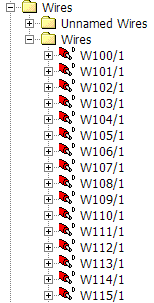
You should have your project schematics linked to the EDS project. Drawing based wires should be displayed in the Cable Scheduler interface in the WIRES FOLDER. Amongst these wires you will have some/many that need to be replaced by the conductors of a cable.
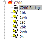
You should also have created a cable (or several) with a fully specified set of cores/conductors where that cable is currently not terminated. This cable could have been created within an EDS single line diagram or within the "cable builder" of Cable Scheduler. This should be the cable you are going to use to replace the wires.
The Process
-
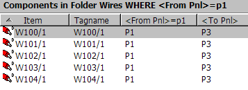
Use the FILTER and SORT options in the WIRES list view to narrow down the number of wires in your view to a workable set. For example you could filter out only wires with a certain destination panel or terminal strip.
-
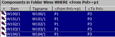
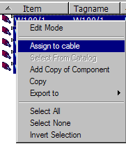
Select the wires you wish to assign to your cable and highlight them.
-
Use the right button to select Assign to Cable.
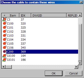
-
Choose your cable.
-
You will be required to select the core/conductor to replace each wire in the "bulk connection" window.
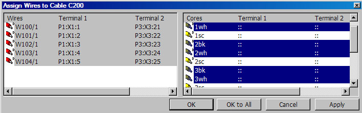
The cores/conductors will now be assigned. The database will be updated. The cores/conductors will now be connected to the terminals that were connected to the wires and the wires and cores/conductors will show a red "A" beside their ICON. This "A" indicates the wires will be replaced by the cores/conductors at the next EDS project update and the wires will vanish from the project.

To Finalise the Assignment
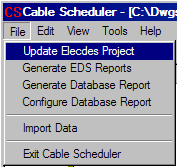
The assigned wires will not be replaced by cable cores/conductors in your EDS project until you either; exit Cable Scheduler, or select FILE->Update Elecdes Project from the menu. You will be asked to confirm the update to the EDS project during this process. This process will take a few seconds.
After the project update is done you will see that the assigned wires are now erased from the Cable Scheduler database as have the red "A"s on the cable cores/conductors. Your schematics will have had the wires replaced by cable cores/conductors and been updated accordingly.
The name of each replaced signal wire will have been placed in a ferrule or label block on each end of the replacement core/conductor – unless the schematic already had a ferrule or label for that signal wire.
Reports and Wiring Diagrams
If you are intending on generating an automatic wiring diagram or automatic connection list reports then you should proceed only after all of your assignment scheduling is completed as this process will cause change to the diagrams and lists as the project terminations are modified.